Software Renderer in Odin from Scratch, Part VIII
16th October 2025 • 22 min read
In this part, we are going to add two new rendering modes. Since we already have the DrawUnlit and DrawFlatShaded procedures, the new procedures will be called DrawTexturedUnlit and DrawTexturedFlatShaded, but Instead of rendering the entire cube in one color, we are going to project an image, commonly called a texture in this context, onto the triangles according to the UV coordinates we prepared for our hardcoded cube mesh in Part IV.
But before that, we first need to be able to load an image from our drive. There are many different image file formats, such as PNG, BMP, JPEG, etc. Some come with compression, some are lossless, and each has its own structure with a different header and must be handled a bit differently when loading.
By loading, I mean reading a file from the drive and storing metadata such as the width and height of the image, as well as the most important part, the array of colors that make up the image itself, in some structure we can then work with in the runtime of our application.
We're going to create a custom struct Texture, with width and height, and colors will be stored in the pixels array in R8G8B8A8 format, which means 8 bits per red, green, and blue channel, and 8 bits for the alpha (transparency) channel, though we're not going to use the alpha channel.
A color in this format can be encoded as a 32-bit number, with helper methods that use bit shifting to pack and unpack individual channels, as each channel can store up to 256 values. However, in Odin we are going to store the color as [4]u8 array type, which allows us to access each channel directly using .r, .g, and .b, a handy accessors for the first, second, and third elements of an array Odin offers for this particular purpose, apart from the .x, .y, and .z accessors we have already used.
And because, as I already wrote, there are many different image formats, we're not going to implement an image loader from scratch. Unlike what we will do later with the OBJ format for loading meshes, here we allow ourselves to be a bit lazy and use the LoadImage and LoadImageColors procedures provided by raylib. This way, our LoadTextureFromFile procedure will consist of just a few lines of code while supporting the most common image file formats.
Implementing texture.odin
Let's start by adding a new file, name it texture.odin, and at the top, after specifying the package name as usual, import raylib and define our Texture struct.
package main

import rl "vendor:raylib"

Texture :: struct {
    width: i32,
    height: i32,
    pixels: [^]rl.Color
}
Notice the format of the pixels. We don't know at compile time how big the loaded image will be, and we want to support images of different sizes. The [^] specifies a multi-pointer, which in Odin represents a foreign (C-like) pointer that behaves like an array. The rl.Color type is an alias defined in Odin's raylib bindings for [4]u8. We used [^]rl.Color (which is the same as [^][4]u8) for pixels because that's what raylib's LoadImageColors procedure returns.
Let's now implement that procedure for loading an image from a file. The procedure will accept a path to an image file and return a Texture it creates.
LoadTextureFromFile :: proc(filename: cstring) -> Texture {
    image := rl.LoadImage(filename)

    texture := Texture{
        width = image.width,
        height = image.height,
        pixels = rl.LoadImageColors(image)
    }

    rl.UnloadImage(image)

    return texture
}
As you can see, raylib helped tremendously, since we delegated all the heavy lifting to LoadImage, which returned an Image object. From this object, we directly get its width and height for our Texture, as well as a multi-pointer to pixels the image is made from, which we get by using the previously mentioned LoadImageColors procedure.
After creating our texture, we have all the data we need, so we can safely remove the image from memory using UnloadImage, also provided by raylib.
I'd like to make a small detour here. You probably already know that Odin is an unmanaged language. This means that when we allocate memory on the heap, we are responsible for freeing that memory when it's no longer needed, so it can be effectively reused for something else, right?
So why is UnloadImage the first time we are doing that? After all, we have allocated memory before. The reason is that, in this renderer, the lifespan of all objects extends through the entire runtime of the application. While we are inside the main loop, we need all those objects to stay in memory, and we only stop needing them after we exit the main loop, but exiting the main loop means quitting the application. So why don't we free any memory at the end of our main procedure?
You might have been taught in school or by other programmers that you should always deallocate any memory you allocate on the heap, probably also with a very strong emphasis on always, and that otherwise you have a memory leak. However, there is no real need to do that here. Once the application quits, the operating system frees all the memory the application has claimed. You can think of the OS as acting like the ultimate garbage collector here.
In fact, explicitly freeing memory right before the application quits would be inefficient, as it would make the shutdown process slower, though the difference would be negligible.
And speaking of memory leaks, not freeing an object from memory when you no longer need it is not necessarily a memory leak per se. A memory leak occurs when your program repeatedly allocates memory, typically inside a loop, without freeing it, thus your application demands more and more memory over time, which eventually slows down the system and can lead to a crash once there's no more memory available.
I'd like to clarify this because I've too often heard dogmatic statements about freeing memory allocated for an object as soon as you no longer need it, as well as misconceptions about what a memory leak is. If you have these misconceptions (I had them for a long time), abandoning them allows you to think about memory allocation differently, and you can start thinking, for example, about the common lifespans of multiple objects, which can lead you to the concept of arena allocators. That topic is too far from the scope of this post, but I do recommend that you Google it.
UV Mapping
Let's get back to the original topic and talk about UV mapping. If you look inside mesh.odin, in the MakeCube procedure, you'll see that we already created an array of UV coordinates, even though we didn't need them at that time.
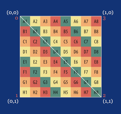
uvs := make([]Vector2, 4)
uvs[0] =  Vector2{1.0, 1.0}
uvs[1] =  Vector2{1.0, 0.0}
uvs[2] =  Vector2{0.0, 0.0}
uvs[3] =  Vector2{0.0, 1.0}

triangles := make([]Triangle, 12)
// Front                 vert.     uvs       norm.
triangles[0] =  Triangle{0, 1, 2,  0, 1, 2,  0, 0, 0}
triangles[1] =  Triangle{0, 2, 3,  0, 2, 3,  0, 0, 0}
// ...
The reason for doing that early was to have a complete mesh structure, so now we don't need to modify our Triangle :: [9]int alias and fiddle with the indices in the triangle array. In this array, the 3rd, 4th, and 5th indices already refer to the UV coordinates for a given triangle.
Also, notice that, for each pair of triangles that make one side of our cube, these indices are the same. This means we will project the same image onto every side of the cube. The following image shows the UV coordinates and their indices in our uvs array, and how they are associated with four vertices that form both triangles.
While rendering a triangle, we will use these UV coordinates to map each pixel from this image, or rather its color value, to be precise, to the correct position on the screen, instead of using the same color as we've done so far, and for that, we're going to once again find our procedure for calculating barycentric weights useful.
Extending sort.odin
I'll explain how UV mapping and texture sampling, which go hand in hand, work in more detail, while we'll be implementing a new rendering pipeline in draw.odin, but before that, we need to implement a procedure that will sort not just our projected points, but also UVs. Open sort.odin and add the following procedure:
SortPointsAndUVs :: proc(
    p1, p2, p3: ^Vector3,
    uv1, uv2, uv3: ^Vector2
) {
    if p1.y > p2.y {
        p1.x, p2.x = p2.x, p1.x
        p1.y, p2.y = p2.y, p1.y
        p1.z, p2.z = p2.z, p1.z
        uv1.x, uv2.x = uv2.x, uv1.x
        uv1.y, uv2.y = uv2.y, uv1.y
    }
    if p2.y > p3.y {
        p2.x, p3.x = p3.x, p2.x
        p2.y, p3.y = p3.y, p2.y
        p2.z, p3.z = p3.z, p2.z
        uv2.x, uv3.x = uv3.x, uv2.x
        uv2.y, uv3.y = uv3.y, uv2.y
    }
    if p1.y > p2.y {
        p1.x, p2.x = p2.x, p1.x
        p1.y, p2.y = p2.y, p1.y
        p1.z, p2.z = p2.z, p1.z
        uv1.x, uv2.x = uv2.x, uv1.x
        uv1.y, uv2.y = uv2.y, uv1.y
    }
}
As you can see, it's fundamentally the same as SortPoints, but since we are sorting the points and the UVs are associated with the vertices these points are projected from, we also need to sort the UVs to make sure they still match the original association. Let's also not forget to extend the definition for explicit overloading at the top:
Sort :: proc {
    SortPoints,
    SortPointsAndUVs
}
Extending draw.odin
Now it's time to implement a new rendering pipeline. Let's start by adding a new procedure DrawTexturedFlatShaded which we'll later call from main.odin inside our main loop:
DrawTexturedFlatShaded :: proc(
    vertices: []Vector3,
    triangles: []Triangle,
    uvs: []Vector2,
    light: Light,
    texture: Texture,
    zBuffer: ^ZBuffer,
    projMat: Matrix4x4,
    ambient:f32 = 0.2
) {
    for &tri in triangles {
        v1 := vertices[tri[0]]
        v2 := vertices[tri[1]]
        v3 := vertices[tri[2]]

        uv1 := uvs[tri[3]]
        uv2 := uvs[tri[4]]
        uv3 := uvs[tri[5]]

        cross := Vector3CrossProduct(v2 - v1, v3 - v1)
        crossNorm := Vector3Normalize(cross)
        toCamera := Vector3Normalize(v1)

        if (Vector3DotProduct(crossNorm, toCamera) >= 0.0) {
            continue
        }

        p1 := ProjectToScreen(projMat, v1)
        p2 := ProjectToScreen(projMat, v2)
        p3 := ProjectToScreen(projMat, v3)

        if (IsFaceOutsideFrustum(p1, p2, p3)) {
            continue
        }

        intensity := math.clamp(Vector3DotProduct(crossNorm, light.direction), ambient, 1.0)

        DrawTexturedTriangleFlatShaded(
            &p1, &p2, &p3,
            &uv1, &uv2, &uv3,
            texture, intensity, zBuffer
        )
    }
}
If you compare the signature of this procedure with that of DrawFlatShaded, you'll notice that the only additions here are the texture and uvs parameters.
The body of the procedure is also quite similar, but we're now also getting the three UV coordinates associated with the triangle, and instead of calling DrawFilledTriangle, we call DrawTexturedTriangleFlatShaded, a procedure we yet need to implement and which will also accept the texture and the three UV coordinates. With the remaining logic, we're already familiar. Let's now implement the DrawTexturedTriangleFlatShaded procedure.
DrawTexturedTriangleFlatShaded :: proc(
    p1, p2, p3: ^Vector3,
    uv1, uv2, uv3: ^Vector2,
    texture: Texture,
    intensity: f32,
    zBuffer: ^ZBuffer,
) {
    Sort(p1, p2, p3, uv1, uv2, uv3)

    FloorXY(p1)
    FloorXY(p2)
    FloorXY(p3)

    // Draw a flat-bottom triangle
    if p2.y != p1.y {
        invSlope1 := (p2.x - p1.x) / (p2.y - p1.y)
        invSlope2 := (p3.x - p1.x) / (p3.y - p1.y)

        for y := p1.y; y <= p2.y; y += 1 {
            xStart := p1.x + (y - p1.y) * invSlope1
            xEnd := p1.x + (y - p1.y) * invSlope2

            if xStart > xEnd {
                xStart, xEnd = xEnd, xStart
            }

            for x := xStart; x <= xEnd; x += 1 {
                DrawTexelFlatShaded(
                    x, y,
                    p1, p2, p3,
                    uv1, uv2, uv3,
                    texture, intensity, zBuffer
                )
            }
        }
    }

    // Draw a flat-top triangle
    if p3.y != p1.y {
        invSlope1 := (p3.x - p2.x) / (p3.y - p2.y)
        invSlope2 := (p3.x - p1.x) / (p3.y - p1.y)

        for y := p2.y; y <= p3.y; y += 1 {
            xStart := p2.x + (y - p2.y) * invSlope1
            xEnd := p1.x + (y - p1.y) * invSlope2

            if xStart > xEnd {
                xStart, xEnd = xEnd, xStart
            }

            for x := xStart; x <= xEnd; x += 1 {
                DrawTexelFlatShaded(
                    x, y,
                    p1, p2, p3,
                    uv1, uv2, uv3,
                    texture, intensity, zBuffer
                )
            }
        }
    }
}
As younoticed for sure, the implementation of DrawTexturedTriangleFlatShaded is also very similar to the DrawFilledTriangle procedure. We still use the flat-top flat-bottom algorithm, but our Sort procedure now calls the SortVerticesAndUVs overload we prepared just a while ago and instead of DrawPixel, we now call DrawTexelFlatShaded, another procedure we yet need to implement, passing the X and Y screen coordinates where the texel (a pixel of color sampled from a texture) should be drawn, projected points, our depth buffer, and in addition also the UV coordinates for each of the projected points and our texture.
DrawTexelFlatShaded is a procedure in which we perform per-pixel texture sampling. In other words, we take a color from our texture and apply it to a specific screen position. As we do this for all positions where we previously drew a predefined color, the triangle, and eventually the entire model, will have the texture image projected onto its surface. Let's start by adding the function signature and declaring ix and iy, the integer variants of the x and y coordinates that are floats, since we need both.
DrawTexelFlatShaded :: proc(
    x, y: f32,
    p1, p2, p3: ^Vector3,
    uv1, uv2, uv3: ^Vector2,
    texture: Texture,
    intensity: f32,
    zBuffer: ^ZBuffer
) {
    ix := i32(x)
    iy := i32(y)
Then, as before, we want to check if the screen coordinate lies outside the frustum, and if so, skip any further calculations by returning early.
if IsPointOutsideViewport(ix, iy) {
    return
}
Now, we calculate the barycentric weights. We have already learned about barycentric weights and implemented the BarycentricWeights procedure in Part VI, and we use these weights to calculate the depth for our depth buffer test. Again, nothing new here.
p       := Vector2{x, y}
weights := BarycentricWeights(p1.xy, p2.xy, p3.xy, p)
alpha   := weights.x
beta    := weights.y
gamma   := weights.z

denom  := alpha*p1.z + beta*p2.z + gamma*p3.z
depth := 1.0 / denom
However, if our depth test passes, we no longer just draw a pixel of a predefined color; now we need to sample that texel from our texture. To do that, we use the barycentric weights again and also the depth to interpolate the UV coordinates for the screen point, then we map these to texture coordinates, and fetch the correct texel from our texture.
zIndex := SCREEN_WIDTH*iy + ix
if depth <= zBuffer[zIndex] {
        interpU := ((uv1.x*p1.z)*alpha + (uv2.x*p2.z)*beta + (uv3.x*p3.z)*gamma) * depth
        interpV := ((uv1.y*p1.z)*alpha + (uv2.y*p2.z)*beta + (uv3.y*p3.z)*gamma) * depth

        texX := i32(interpU * f32(texture.width )) % texture.width
        texY := i32(interpV * f32(texture.height)) % texture.height

        tex  := texture.pixels[texY*texture.width + texX]
Yet, we want the texel to be shaded, and since we have already calculated the intensity for the entire triangle, we simply multiply each color channel of the texel by this intensity. Then we finally draw the texel on the screen and update the depth buffer, which concludes the entire implementation of a pipeline for flat-shaded rendering with a texture.
One last thing we're going to add before we leave draw.odin for today is the DrawTexturedUnlit procedure, an entry point for unlit rendering with a texture. This one is going to be super simple. We don't need to calculate intensity, so we can reuse the IsBackFace procedure, and as the intensity for the DrawTexturedTriangleFlatShaded call, we simply pass 1.0, and we're done.
DrawTexturedUnlit :: proc(
    vertices: []Vector3,
    triangles: []Triangle,
    uvs: []Vector2,
    texture: Texture,
    zBuffer: ^ZBuffer,
    projMat: Matrix4x4
) {
    for &tri in triangles {
        v1 := vertices[tri[0]]
        v2 := vertices[tri[1]]
        v3 := vertices[tri[2]]

        uv1 := uvs[tri[3]]
        uv2 := uvs[tri[4]]
        uv3 := uvs[tri[5]]

        if IsBackFace(v1, v2, v3) {
            continue
        }

        p1 := ProjectToScreen(projMat, v1)
        p2 := ProjectToScreen(projMat, v2)
        p3 := ProjectToScreen(projMat, v3)

        if (IsFaceOutsideFrustum(p1, p2, p3)) {
            continue
        }

        DrawTexturedTriangleFlatShaded(
            &p1, &p2, &p3,
            &uv1, &uv2, &uv3,
            texture,
            1.0, // Unlit
            zBuffer
        )
    }
}
Extending main.odin
Before we add our two new rendering modes in main.odin, create a new directory, name it assets, and then download the following image into this directory.

Now, in the main procedure, after we create a mesh, create a texture using our LoadTextureFromFileprocedure, with a path to the image you just downloaded.
texture := LoadTextureFromFile("assets/uv_checker.png")
Then, increment the renderModesCount to 6.
renderModesCount :: 6
And finally, add calls to the DrawTexturedUnlit and DrawTexturedFlatShaded procedures for cases 4 and 5 in the switch over renderMode, respectively.
switch renderMode {
    case 0: DrawWireframe(mesh.transformedVertices, mesh.triangles, projectionMatrix, rl.GREEN, false)
    case 1: DrawWireframe(mesh.transformedVertices, mesh.triangles, projectionMatrix, rl.GREEN, true)
    case 2: DrawUnlit(mesh.transformedVertices, mesh.triangles, projectionMatrix, rl.WHITE, zBuffer)
    case 3: DrawFlatShaded(mesh.transformedVertices, mesh.triangles, projectionMatrix, light, rl.WHITE, zBuffer)
    case 4: DrawTexturedUnlit(mesh.transformedVertices, mesh.triangles, mesh.uvs, texture, zBuffer, projectionMatrix)
    case 5: DrawTexturedFlatShaded(mesh.transformedVertices, mesh.triangles, mesh.uvs, light, texture, zBuffer, projectionMatrix)
}
Conclusion
That's it for today. If you now compile and run the program (odin run . -o:speed), you should see a flat shaded cube with UV checker texture projected on its surface, and if you press the left arrow, you should see the same cube just without shading.
You should still be able to move the cube around with the WSADQD keys, rotate it with the IJKLUO keys, scale it using + and -, and cycle through now six rendering modes with the left and right arrows. If anything doesn't work as expected, compare your implementation with the one in the Part 8 directory in this GitHub repository.
Enjoyed this article? Support my work ❤️
All content on this blog, which I've already put hundreds of hours into, is and always will be free.
No ads. No paywalls. No tricks.
I've personally paid for a lot of educational content, but I strongly believe knowledge should be accessible to everyone.
I also pay to keep this blog up and running, and if you like what I do here, if it has helped you, and you would like to support me, you can

Even a small contribution, the price of a coffee, is very much appreciated.
Other Parts of This Series
- Software Renderer in Odin from Scratch, Part I
- Software Renderer in Odin from Scratch, Part II
- Software Renderer in Odin from Scratch, Part III
- Software Renderer in Odin from Scratch, Part IV
- Software Renderer in Odin from Scratch, Part V
- Software Renderer in Odin from Scratch, Part VI
- Software Renderer in Odin from Scratch, Part VII
- Software Renderer in Odin from Scratch, Part VIII
- Software Renderer in Odin from Scratch, Part IX
- Software Renderer in Odin from Scratch, Part X
- Software Renderer in Odin from Scratch, Part XI
- Software Renderer in Odin from Scratch, Part XII
- Software Renderer in Odin from Scratch, Part XIII
- Software Renderer in Odin from Scratch, Part XIV


